Description
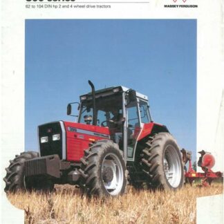
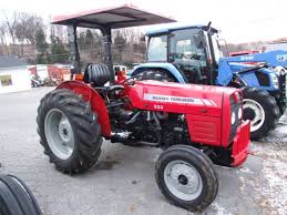
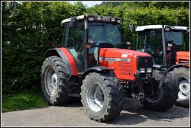
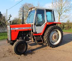
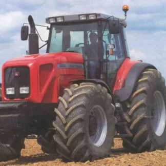
Massey Ferguson 6400 Series Tractor Service Repair Manual PDF Download
This authentic Massey Ferguson service repair manual contains high quality images, diagrams, instructions to help you to operate, maintenance, diagnostic, and repair your truck. This document is printable, without restrictions, contains searchable text, bookmarks, crosslinks for easy navigation.
This manual contains detailed maintenance, service, repair and troubleshooting procedures for Massey Ferguson 6400 Series Tractors. The service manual is a must for all Massey Ferguson 6400 Series Tractor mechanics and contains over 4,400 pages of the latest service information for the tractor. Print off the pages including diagrams and illustrations you need at any time and save time and money on repair.
Topics list:
Introduction Specifications
Using the manual
SPECIFICATIONS General specifications
SPECIFICATIONS Ground speeds
SPECIFICATIONS Dimensions
SPECIFICATIONS Capacities
Miscellaneous
Splitting the tractor
Splitting Front frame / Perkins engine
Splitting Front frame / Sisu engine
Splitting the front frame/Sisu engine MF 6497 6499
Splitting Perkins Engine / GBA20 Gearbox
Perkins/GTA2520 engine separation
Splitting – Sisu Engine / GBA10 Gearbox
Splitting the Sisu engine/GTA1030
Sisu engine/GTA1540 transmission separation
Splitting GBA20 gearbox / Centre housing
GBA25/GPA20 separation
GBA10/GPA30 separation
Intermediate housing/centre housing separation GPA30
Splitting PTO housing / Centre housing
Centre housing/PTO housing separation GPA30
Reinforcements GTA1040
Reinforcements GTA1030
Reinforcements GTA1540
PERKINS ENGINE – General information
SISU ENGINE – General information
SISU ENGINE – Engine/GTA1030 transmission link
SISU ENGINE – Engine/GTA2520 and GTA1540 transmission connection
Note: Engine repair manuals sold separately.
Gearbox
General GBA20 operation
GBA20 input unit
GBA20 Power shuttle
GBA20 Dynashift
GBA20 Selector rails
GBA20 Output shaft
GBA20 Mainshaft
GBA20 Layshaft
GBA20 Super Creeper unit
GBA10 General Operation
GBA10 Input unit
GBA10 PowerShuttle
GBA10 Dynashift
GBA10 Selector cover
GBA10 Selector rails
GBA10 Output shaft
GBA10 Mainshaft
GBA20 Layshaft
GBA10 Creeper unit
GBA25 General Operation
GBA25 PowerShuttle
GBA25 Powershift module
GBA25 Robotic mechanical gearbox
GBA25 Creeper unit
GBA25 Super Creeper unit
GBA15 General Operation
GBA15 Power Shuttle
GBA15 Powershift module
GBA15 Robotic mechanical gearbox
GBA15 Creeper
Rear axle
General GPA20 operation
GPA 20 Normal Duty trumpet housings
GPA20 Super Heavy Duty trumpet housings
GPA20 brake pistons
GPA20 handbrake unit and control
GPA20 differential
GPA20 Hitch / Linkage
GPA20 Auto hitch
GPA20 rear wheels / hubs
GPA40 General Operation
GPA40 Normal Duty trumpet housings
GPA40 Heavy Duty trumpet housings
GPA40 Sealed Heavy Duty trumpet housings
GPA40 Trumpet housings with composite final drive
GPA40 Brake pistons
GPA40 Pinion
GPA40 Hand brake unit and control
GPA40 5″ differential and multidisc lock
GPA40 7″ differential and multidisc lock
GPA40 Hitch and linkage
GPA40 Auto hitch
GPA40 Rear wheels/hubs
GPA30 General Operation
GPA30 Heavy Duty Sealed trumpet housings
GPA30 Trumpets housings with composite drive unit
GPA30 Brake pistons
GPA30 Drive pinion
GPA30 Handbrake unit and control
GPA30 7″ differential unit and multidisc lock
GPA30 Hitch and linkage mechanisms
GPA30 Auto hitch
GPA30 Rear wheels/Hubs
Power take off
General GPA20 operation
Layshaft Driving pinion PTO brake
Removable PTO shaft
Shiftable PTO shaft
GSPTO
PTO clutch
GPA40 General Rear PTO operation
GPA40 Intermediate shaft and driving gears
GPA40 Output shaft and brake
GPA40 GSPTO
GPA40 Clutch
GPA30 General Operation
GPA30 Intermediate shafts Driving pinions
GPA30 Interchangeable output shaft
GPA30 Shiftable output shaft
GPA30 1000 rpm output shaft
GPA30 PTO brake and clutch
Front axle
General
Carraro final drive units
Carraro differential
GPA20 Carraro bearings and transmission shafts
GPA40 Carraro bearings and transmission shafts
GPA20 4WD clutch assembly
4WD GPA40 clutch
Carraro suspension
Carraro troubleshooting
CARRARO 20.48 General
CARRARO 20.48 Final drive units
CARRARO 20.48 Differential
CARRARO 20.48 GPA30 Transmission shaft and bearing
4 WD GPA30 Clutch
CARRARO 20.48 Suspension
CARRARO 20.48 Trouble shooting
DANA front axle General:
2WD front axle beam
Hydraulics
Description of Load Sensing system
LS hydraulic tests
Right hand LS cover plate
Twin flow load sensing right hand hydraulic cover
Left hand cover Open Centre
Left hand LS cover plate
Twin flow load sensing left hand cover
Assisted brake master cylinders
High pressure brakes General
High pressure braking high pressure braking unit
High pressure braking block/valve assembly
LS trailer braking
Twin flow load sensing trailer braking
Pneumatic trailer braking
ParkLock GPA40
Lift control spool valve Open Centre
LS and TFLS lift control spool valve
Auxiliary spool valves Open Centre
LS and TFLS auxiliary mechanical spool valves GPA20 and GPA40
LS auxiliary mechanical spool valves GPA30
LS and TFLS electrohydraulic auxiliary spool valves GPA20 and GPA40
LS electrohydraulic auxiliary spool valves GPA30
Steering column
Hydrostatic steering Open Centre
LS and TFLS hydrostatic steering 125/160 cm3
LS and TFLS hydrostatic steering 80/205 cm3 and 80/240 cm3
Steering rams
17 bar valve Open Centre
17 bar twin flow load sensing valve
GBA20 Power Shuttle control unit
GBA10 PowerShuttle control unit
CARRARO suspended front axle control unit
Electrical equipment
Fuse boxes
ELECTRICAL DIAGRAMS Cab equipment
ELECTRICAL DIAGRAMS Engine equipment
ELECTRICAL DIAGRAMS Lighting
ELECTRICAL DIAGRAMS Supply of electronic boxes
Electronics
EEM Perkins Description
Perkins ELECTRONIC INJECTION Tests and diagnostics
Perkins ELECTRONIC INJECTION Electrical Diagrams
EEM2 SisuDiesel Description
ELECTRONIC INJECTION SisuDiesel Programming
SisuDiesel ELECTRONIC INJECTION Tests and diagnostics
SisuDiesel ELECTRONIC INJECTION Error codes
SisuDiesel ELECTRONIC INJECTION Electrical Diagrams
DCC2 (Dynashift) Programming and setting parameters
DCC2 (Dynashift) Error codes
DCC2 (Dynashift) Calibrations and constants
DCC2 (Dynashift with Autotronic 5) Programming and setting parameters
DCC2 (Dynashift with Autotronic 5) Tests and diagonostics
DCC2 (Dynashift with Autotronic 5) Error codes
DCC2 (Dynashift with Autotronic 5) Calibrations, constants and adjustments
DCC2 (Dynashift with Autotronic 5) Electrical diagrams
DCC2 (Dyna 6) Description
DCC2 (Dyna 6) Programming and setting parameters
DCC2 (Dyna 6) Tests and diagnostics
DCC2 (Dyna 6) Error codes
DCC2 (Dyna 6) Calibrations, constants and adjustments
DCC2 (Dyna 6) Electrical diagrams
AUTOTRONIC 3 Programming and setting parameters 6400
AUTOTRONIC 3 Tests and diagnostics 6400
AUTOTRONIC 3 Error codes 6400
AUTOTRONIC 3 Calibration and adjustments 6400
AUTOTRONIC 3 Electrical diagrams 6400
AUTOTRONIC 5 Dynashift Description
AUTOTRONIC 5 Dynashift Programming and setting parameters
AUTOTRONIC 5 Dynashift Tests and diagnostics
AUTOTRONIC 5 Dynashift Error codes
AUTOTRONIC 5 Dynashift Calibration and adjustments
AUTOTRONIC 5 Dynashift Electrical diagrams
Autotronic 5 Dyna 6 Description
AUTOTRONIC 5 Dyna 6 Programming and setting parameters
AUTOTRONIC 5 Dyna 6 Tests and diagnostics
Autotronic 5 Dyna 6 Error codes
AUTOTRONIC 5 Dyna 6 Calibration
AUTOTRONIC 5 Dyna 6 Electrical diagrams
AUTOTRONIC 5 ParkLock GPA40 (Autotronic 3) Tests and diagnostics
AUTOTRONIC 5 ParkLock GPA40 (Autotronic 3) Error codes
AUTOTRONIC 5 ParkLock GPA40 (Autotronic 3) Electrical diagrams
EHRC LINKAGE Description
EHRC Linkage Setting parameters
EHRC Linkage Tests and diagnostics
EHRC Linkage Error codes
EHRC Linkage Adjustments
EHRC Linkage Electrical diagrams 6400/7400
AUTOTRONIC 5 Linkage Programming and setting parameters
AUTOTRONIC 5 Linkage Tests and diagnostics MF6400/7400/8400
AUTOTRONIC 5 Linkage Error codes MF6400/7400/8400
AUTOTRONIC 5 Linkage Calibration and adjustments
AUTOTRONIC 5 Linkage Electrical diagrams MF6400/7400/8400
DATATRONIC 2 Programming and setting parameters
DATATRONIC 2 Tests and diagnostics
DATATRONIC 2 Error codes
DATATRONIC 2 Calibration
DATATRONIC 2 Electrical diagrams 6400 / 7400
DATATRONIC 3 Programming
DATATRONIC 3 Calibration and adjustments
DATATRONIC 3 Electrical diagrams
SMS Description
SMS JOYSTICK / FingerTIP Setting parameters
SMS JOYSTICK/FingerTIP Tests and diagnostics
SMS JOYSTICK / FingerTIP Error codes
SMS JOYSTICK Settings
SMS JOYSTICK Electrical diagrams EHRC linkage
SMS JOYSTICK/FingerTIP Electrical diagrams Auto 5 linkage
AUTOTRONIC 5 CARRARO suspended front axle Programming
AUTOTRONIC 5 CARRARO suspended front axle Tests and diagnostics
AUTOTRONIC 5 CARRARO Suspended front axle Error codes
AUTOTRONIC 5 CARRARO suspended front axle Calibration and adjustments
AUTOTRONIC 5 CARRARO suspended front axle Electrical diagrams
Autotronic 5 DANA Suspended front axle Description
AUTOTRONIC 5 DANA suspended front axle Programming and setting parameters
AUTOTRONIC 5 DANA suspended front axle Tests and diagnostics
AUTOTRONIC 5 DANA suspended front axle Error codes
AUTOTRONIC 5 DANA suspended front axle Calibration and adjustments
AUTOTRONIC 5 DANA suspended front axle Electrical diagrams
Cab and Equipment
Suspended cab
Air conditioning
Standard air conditioning
Standard air conditioning
Automatic air conditioning
AUTOMATIC AIR CONDITIONING Tests and diagnostics
AUTOMATIC AIR CONDITIONING Error codes
AUTOMATIC AIR CONDITIONING Electrical diagrams
Refilling the unit
Covers: Massey Ferguson 6400 Series Tractors
- MF-6445
- MF-6455
- MF-6460
- MF-6465
- MF-6470
- MF-6475
- MF-6480
- MF-6485
- MF-6490
- MF-6495
- MF-6497
- MF-6499
Pages: 4,420
Format: PDF file
File size: 301mb
Compatibility: Windows/Mac/Tablet
Notes: Instant digital download only – no printed copy or CD-ROM media.

